- 您现在的位置:买卖IC网 > Sheet目录19096 > LD200600 (Red Lion Controls)COUNTER 6 DIGIT 2.25" 120VAC RED
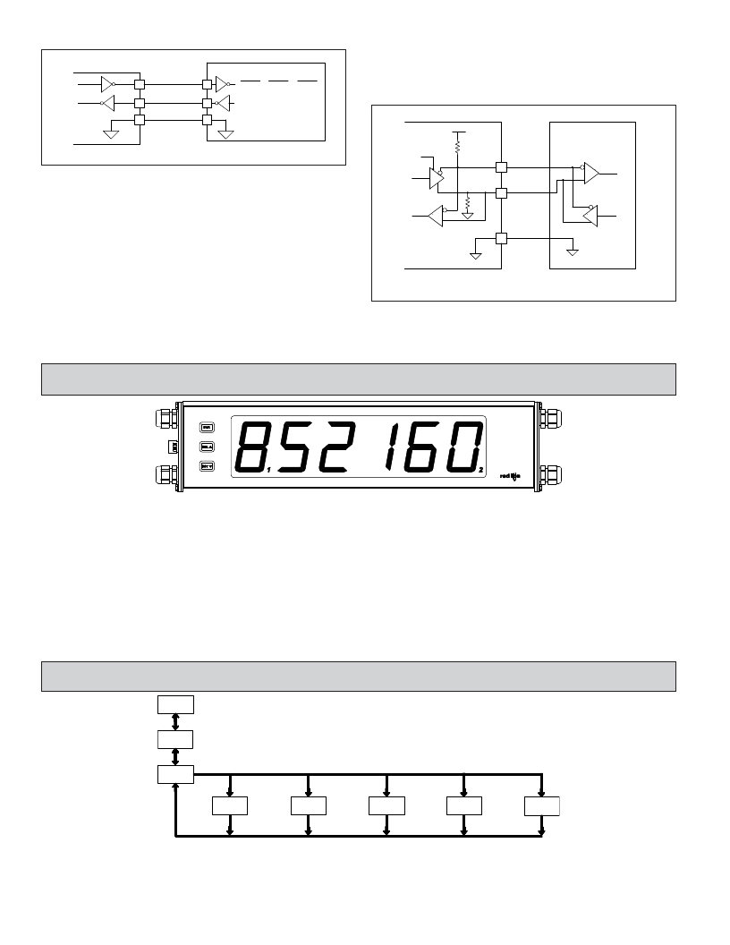
RS232 Communications
RS485 Communications
LD METER (DTE)
1
TXD
RXD
RECEIVING DEVICE
DB25 DB25 DB9
DCE DTE DTE
2 3 2
The RS485 communication standard allows the connection of up to 32
devices on a single pair of wires, distances up to 4,000 ft. and data rates as high
as 10M baud (the LD is limited to 38.4k baud). The same pair of wires is used
to both transmit and receive data. RS485 is therefore always half-duplex, that is,
2
RXD
TXD
3
2
3
data cannot be received and transmitted simultaneously.
3
COMM.
5
7
5
LD METER
+5V
RECEIVING DEVICE
Terminal Block Connection Figure
Transmit
Enable
47K
5
B (-)
RS232 is intended to allow two devices to communicate over distances up to
50 feet. Data Terminal Equipment (DTE) transmits data on the Transmitted Data
(TXD) line and receives data on the Received Data (RXD) line. Data Computer
47K
4
A (+)
Equipment (DCE) receives data on the TXD line and transmits data on the RXD
line. The LD emulates a DTE. If the other device connected to the meter also
emulates a DTE, the TXD and RXD lines must be interchanged for
communications to take place. This is known as a null modem connection. Most
printers emulate a DCE device while most computers emulate a DTE device.
Some devices cannot accept more than two or three characters in succession
3
COMM.*
without a pause in between. In these cases, the meter employs a busy function.
As the meter begins to transmit data, the RXD line (RS232) is monitored to
* OPTIONAL
Terminal Block Connection Figure
determine if the receiving device is “busy”. The receiving device asserts that it
is busy by setting the RXD line to a space condition (logic 0). The meter then
suspends transmission until the RXD line is released by the receiving device.
Sections 4 and 5 apply to Programmable Models Only
4.0 R EVIEWING THE F RONT P ANEL K EYS AND D ISPLAY
KEY
PAR
SEL ?
RST ?
DISPLAY MODE OPERATION
Access Programming Mode
Index display through selected displays
Resets count display(s) and/or outputs
PROGRAMMING MODE OPERATION
Store selected parameter and index to next parameter
Advance through selection list/select digit position in
parameter value
Increment selected digit position of parameter value
OPERATING MODE DISPLAY DESIGNATORS
“ ? ” - To the left of the display is the rate value.
- Counter A has no designator.
“ 1 ” - To the right of digit 6 indicates setpoint 1 output status.
“ 2 ” - To the right of digit 1 indicates setpoint 2 output status.
“ ? ” - To the left of the display is the Counter B value (dual count or batch).
Pressing the SEL ? key toggles the meter through the selected displays. If display scroll is enabled, the display will toggle automatically every four seconds
between the rate and count values.
5.0 P ROGRAMMING
THE
M ETER
DISPLAY
MODE
PAR
NO
OVERVIEW
PROGRAMMING MENU
Display and Front
Setpoint
Serial
Input Setup
Rate Setup
Panel Key
Output
Setup
Pro
Parameters
SEL
PAR
1-INP
Parameters
PAR
2-rAtE
Parameters
PAR
3-dSP
Parameters
PAR
4-SPt
Parameters
PAR
5-SEr
PROGRAMMING MODE ENTRY (PAR KEY)
It is recommended all programming changes be made off line, or before
installation. The meter normally operates in the Display Mode. No parameters
can be programmed in this mode. The Programming Mode is entered by
pressing the PAR key. If it is not accessible, then it is locked by either a security
code or a hardware lock.
6
MODULE ENTRY (SEL ? & PAR KEYS)
The Programming Menu is organized into five modules. These modules group
together parameters that are related in function. The display will alternate between
??? and the present module. The SEL ? key is used to select the desired module.
The displayed module is entered by pressing the PAR key.
发布紧急采购,3分钟左右您将得到回复。
相关PDF资料
ASD1-33.000MHZ-ECT
OSCILLATOR 33.000 MHZ 3.0V SMD
LD200400
COUNTER 4 DIGIT 2.25" 120VAC RED
ASD1-12.000MHZ-ECT
OSCILLATOR 12.000 MHZ 3.0V SMD
PAXLC600
COUNTER 6-DIGIT BI-DIR COUNT
CUB7P120
COUNTER 8-DIGIT VOLTAGE RED
5652F1-5V
LED RED T1 QUAD RT ANG 5V PCB
FXO-HC526R-125
OSC 125 MHZ 2.5V HCMOS SMD
183566
LED T-1 28V .100" BI-PIN BASE
相关代理商/技术参数
LD2006P0
功能描述:COUNTER 6 DIGIT DUAL 2.25" RED RoHS:是 类别:工业控制,仪表 >> 计数器 系列:LD 其它有关文件:Declaration of Conformity 标准包装:1 系列:99766 计数速率:25Hz 数字/字母数:5 输入类型:机电式脉冲 输出类型:- 电源电压:24V 显示器类型:十进制拨轮
LD-201
制造商:ROHM 制造商全称:Rohm 功能描述:Flat displays
LD201C105KAB1A
功能描述:多层陶瓷电容器MLCC - SMD/SMT 100volts 1uF 10% 2220 X7R RoHS:否 制造商:American Technical Ceramics (ATC) 电容:10 pF 容差:1 % 电压额定值:250 V 温度系数/代码:C0G (NP0) 外壳代码 - in:0505 外壳代码 - mm:1414 工作温度范围:- 55 C to + 125 C 产品:Low ESR MLCCs 封装:Reel
LD201C105KAB2A
功能描述:多层陶瓷电容器MLCC - SMD/SMT 1.0UF 100V 10% RoHS:否 制造商:American Technical Ceramics (ATC) 电容:10 pF 容差:1 % 电压额定值:250 V 温度系数/代码:C0G (NP0) 外壳代码 - in:0505 外壳代码 - mm:1414 工作温度范围:- 55 C to + 125 C 产品:Low ESR MLCCs 封装:Reel
LD201C105KAB9A
功能描述:多层陶瓷电容器MLCC - SMD/SMT 100volts 1uF 10% 2220 X7R RoHS:否 制造商:American Technical Ceramics (ATC) 电容:10 pF 容差:1 % 电压额定值:250 V 温度系数/代码:C0G (NP0) 外壳代码 - in:0505 外壳代码 - mm:1414 工作温度范围:- 55 C to + 125 C 产品:Low ESR MLCCs 封装:Reel
LD201C475KAB2A
功能描述:多层陶瓷电容器MLCC - SMD/SMT 100volts 4.7uF 10% 2220 X7R RoHS:否 制造商:American Technical Ceramics (ATC) 电容:10 pF 容差:1 % 电压额定值:250 V 温度系数/代码:C0G (NP0) 外壳代码 - in:0505 外壳代码 - mm:1414 工作温度范围:- 55 C to + 125 C 产品:Low ESR MLCCs 封装:Reel
LD201C475KAX2A
功能描述:多层陶瓷电容器MLCC - SMD/SMT 100volts 4.7uF 10% X7R 2220 SIZE
RoHS:否 制造商:American Technical Ceramics (ATC) 电容:10 pF 容差:1 % 电压额定值:250 V 温度系数/代码:C0G (NP0) 外壳代码 - in:0505 外壳代码 - mm:1414 工作温度范围:- 55 C to + 125 C 产品:Low ESR MLCCs 封装:Reel
LD2021MG
制造商:未知厂家 制造商全称:未知厂家 功能描述:Optoelectronic
